
UNDERSTANDING QUANTUM INFORMATION
Qubits
While similar in functionality to classical bits, qubits are fundamentally different.
Summary
There are a variety of quantum bits, or qubits, that are used in quantum technology. This white paper discusses the different types of qubits and the fundamentals of how qubits are used in a quantum network, including how qubits are encoded and how to address quantum errors.
Introduction
Quantum technologies use quantum bits (qubits) to perform computations, process information, and to send and receive data. While similar in functionality to classical bits, qubits are fundamentally different. Classical bits represent either a 0 or a 1. Qubits can exist in superpositions of states and can become entangled with one another, unlocking entirely new possibilities for computation and communication.
Different physical implementations (superconducting, trapped ions, photons, or solid-state) have unique strengths and limitations. Each platform offers different lifetimes, error characteristics, and connectivity. Choosing the right qubit platform for your specific application helps to ensure your success.
A Metro Area Network (MAN) example
Throughout this white paper, we use the example of a Metro Area Network to ground the concepts we cover in a real-world use case.
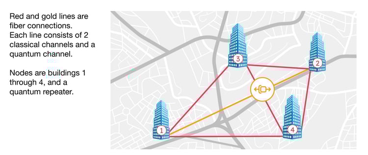
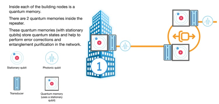
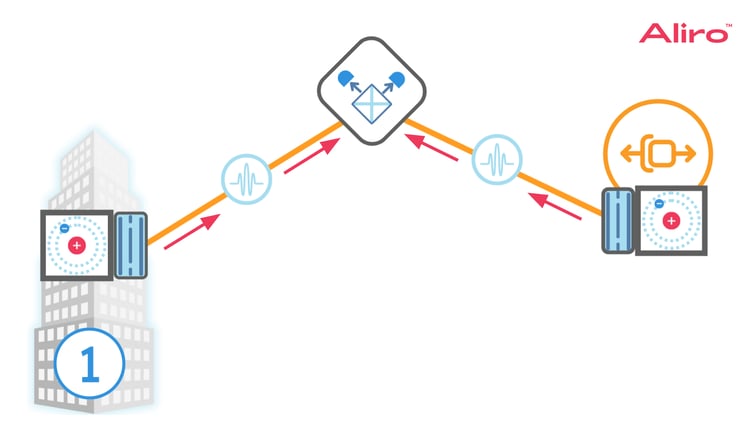
In our example Metro Area Network, there are four buildings labeled one through four. Each of these buildings is a quantum network node: each building will have stationary qubits which will be able to store quantum information and also transmit quantum information over the network. A quantum repeater is also used in this example, and is represented by the gold symbol within the gold circle. The red and gold lines that connect the buildings and the quantum repeater, these lines represent fiber connections, and these fiber connections include a real-time classical channel, a non-real time classical channel, and a quantum channel.
––––––––––––––––––––––––––––––––––––––––––––––––––––––
The focus of this paper is on the quantum channel, but more about these other channels can be found in the on-demand webinar How to Integrate a Quantum Network with Your Existing Network.
––––––––––––––––––––––––––––––––––––––––––––––––––––––
In this example, these red connections are under 100 kilometers, and the gold connection with the quantum repeater is over 100 kilometers. In a quantum network, quantum repeaters provide a way to transmit quantum information with relatively low loss, even over a longer distance connection. It acts as a relay station, but in a very different way from the classical version.
What is a qubit?
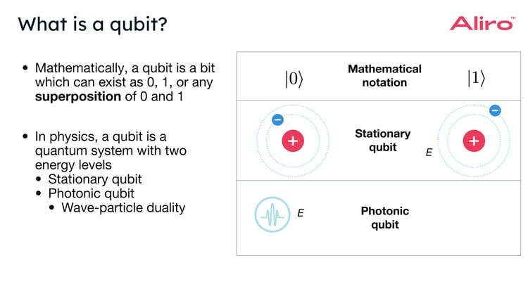
Mathematically, a qubit is a bit which can exist as 0, 1, or any superposition of zero and one. Qubits are often written in ket notation, which looks like a number that represents the quantum state within a line and a bracket. Below, at the top of the chart, is a zero ket and a one ket, representing different quantum states.
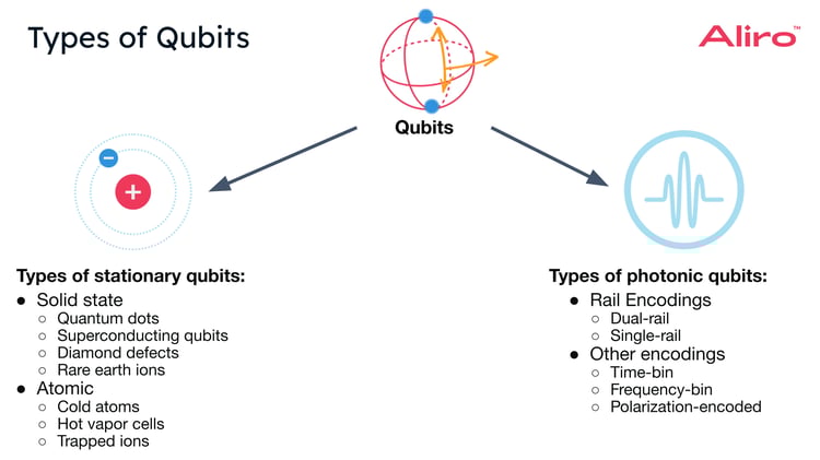
In a quantum network, we can think about having two different types of qubits: stationary qubits and photonic qubits.
 Stationary qubits are these qubits which encode information at the quantum repeaters or at the quantum nodes. They generally remain in one place and don't move. Photonic qubits will often carry quantum information between nodes or between nodes and repeaters.
Physically, a stationary qubit can be thought of as a system with two energy levels. Below the ket notation is a visualization of a qubit in the zero state and a stationary qubit in the one state. In physics, a qubit is a system that has a positively charged nucleus and a negatively charged electron that could be found in one of two different energy levels as indicated by the orbit around the nucleus, and also in any superposition of these two energy levels. Because opposites attract, the positive charge will want to be close to the negative charge, and it will require energy to pull the negative charge away from the positive charge. A lower energy state would be a state where the electron and neutron are closer together, whereas a higher energy state would be a state where they're further apart. Because this is a quantum system, it’s possible to have superpositions between these two energy states.
There are different ways to encode quantum information within a photonic qubit. These photonic qubits are just photons, or particles of light, encoded with quantum information. They behave as if they have two energy levels, with information stored in two possible optical states. In addition, because of the principle of wave-particle duality, photons have both particle-like properties and wave-like properties. Because of these wave-like properties, a photonic qubit has a frequency and a wavelength associated with it. How photonic qubits are encoded and the role of their particle and wave-like properties are discussed in more detail later in this paper.
Stationary qubits and photonic qubits can exist independently, but quantum networks will require both types of qubits. There are exchanges of quantum information between these two types of qubit in a quantum network that uses quantum repeaters for extending the distance of quantum links, as well as connecting quantum processing units / quantum computers for greater computational power.
What does a qubit do in a quantum network?
Qubits carry information in a quantum network.
Pictured below is a single branch of the example Metro Area Network: the link between the Quantum Repeater and Building One.
 This graphic shows two photons, and they're traveling in the direction of the green arrows. One of the photons is traveling towards Building One, and the other photon is traveling towards the Quantum Repeater. The light blue wavy line between the photons indicates that these photons are entangled. This doesn't mean there's any sort of physical connection between them, but rather there is some shared information or shared quantum state between the two photons, where if you measure one photon, the results will be correlated with the measurement of the other photon.
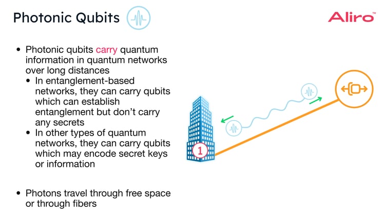
Photonic qubits are used to carry quantum information in quantum networks over long distances. Entanglement-based quantum networks carry photonic qubits that establish entanglement between nodes and teleport information. These entangled qubits won't contain any secret information. However, in other types of quantum networks, such as QKD-based quantum networks, these photonic qubits may be carrying secret keys or other information.
Photons can either travel through free space or travel through fibers. In the Metro Area Network example, the photons travel through fibers. This is a practical decision, as it's difficult to have a free space quantum network in a city setting where there are a lot of physical obstacles that could block the photons from being received. In this case, it’s easier to use fibers instead.
Properties of Photonic Qubits
There are certain properties of photonic qubits that make them particularly suited to be used in networking for quantum communication.
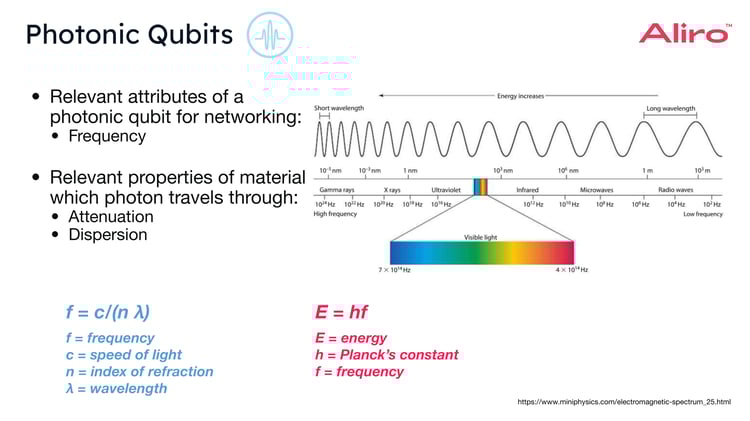
One attribute of photonic qubits that's important for networking is the frequency of the photon. The frequency of a photon is related to the photon's energy, as well as the photon's wavelength. So it's related through the equation E = hf, where E is energy, h is Planck's constant, and f is frequency.
You might be familiar with the electromagnetic spectrum, and the idea that light is electromagnetic radiation, and can exist at different wavelengths and at different energies. For quantum networking, visible light and the infrared zone of light are the most relevant frequencies. In addition to these qualities of photons, there are also properties pertaining to the material that the photon will travel through that are relevant to the operation of the network. These properties include attenuation, which is the loss of this photon will experience in a particular material, such as optical fiber. Attenuation is usually measured in decibels, or in decibels per kilometer. Dispersion is another relevant property of the channel a photonic qubit travels through. Dispersion is how the refractive index of the material changes with wavelength. Dispersion essentially shows how light of different wavelengths will have different speeds traveling through the same material.
Encoding Photonic Qubits
Photonic qubits are encoded by assigning the 0 and 1 states to different patterns of light, which are distinct enough (orthogonal) that a photon can only be in one or the other, never both at once.
There are two main ways to describe how a photonic qubit is encoded:
- How many light patterns (modes) you use to represent it. This is called rail-based encoding.
- Which physical property of the photon (polarization, time, frequency, etc) creates those patterns. When this type of encoding is used, it is referred to as the degree of freedom.
Photonic Qubit Encoding: Rail-based Encoding
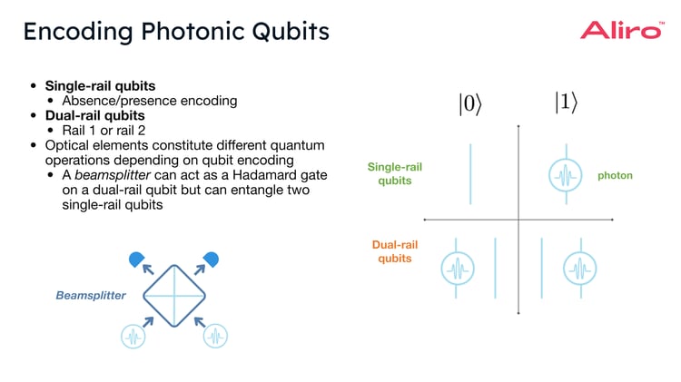 In single-rail encoding, you use one mode. Single-rail encoding is an absence / presence encoding. In this type of encoding, zero state is the absence of a photon, and the one state is the presence of a photon, but the photon may also be in a superposition of absence and presence.
Another way to encode photons is through dual-rail encoding. In dual-rail encoding, there are two modes for the photon to occupy. The state that the photon is in will depend on the rail that it's on. In our example, if the photonic qubit is on the left rail, then it is in the zero state, and if the photonic qubit is on the right rail, it will be in the one state. The photon could also exist in a superposition of these rails. (Please note that “rails” don’t refer to separate fiber channels. Dual-rail encoding uses two orthogonal modes, which can be in the same fiber.)
It’s important to note here that the same optical component can implement different quantum operations depending on how the photonic qubit is encoded. So for instance, a beam splitter is a commonly used optical element. In a dual-rail encoded qubit, a beam splitter acts as a Hadamard gate. A Hadamard gate is a fundamental quantum logic gate that transforms a qubit into a superposition of its states. In other words, when applied to a dual-rail qubit, it creates an equal probability of measuring the qubit as either 0 or 1. A beam splitter can also be used to entangle two single-rail qubits, in combination with Bell state measurement. In quantum networks, this is part of the process of entangling two distant stationary qubits.
Photonic Qubit Encoding: Degrees of Freedom
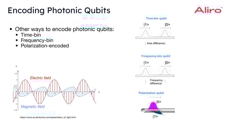 Time-bin encoding. This type of encoding uses a time difference to constitute the state that the photon is in: the photon arrives at an early time or it arrives at a later time.
Frequency-bin encoding. This is very similar to time-bin encoding, but in the frequency domain, using different frequencies to determine which state the photon is in. The two modes are two frequencies, f₁ or f₂.
Polarization encoding. Polarization is a property of light, which will tell you the direction that the electric field is oscillating in. The two modes of polarization are horizontal or vertical. Since light is electromagnetic radiation, it can be visualized as a wave with both an electric field oscillating and a magnetic field that oscillates. In the image above, the wave is traveling along the x axis, but the electric field is oscillating in the y direction. You could imagine rotating this wave so that the electric field oscillates in the z direction, or in any vector on this plane. This would change its polarization. Orthogonal (mutually independent and non-overlapping) polarizations can be used to constitute the zero state and the one state.
Let's return to the Metro Area Network example, and zoom into this connection between Building One and the Quantum Repeater.
At Building One, there is a quantum memory that consists of one or more stationary qubits and a transducer. The transducer converts the photons emitted from the quantum memory into a frequency that is well suited for the optical fibers carrying the qubits. The Quantum Repeater will have quantum memories with one or more stationary qubits and transducers. Photonic qubits effectively carry quantum information through the fiber between these memories, enabling the connection.
Stationary Qubits
In a quantum network, photonic qubits transmit quantum information across distances, and stationary qubits store quantum information until it is needed. Stationary qubits are also used for a lot of other quantum processes, like error correction and entanglement purification. Stationary qubits are also used in quantum computers and quantum sensors.
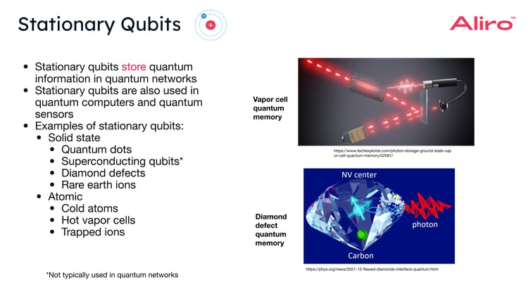
Examples of stationary qubits in the solid state include quantum dots, diamond defects, rare earth ions, and superconducting qubits. Superconducting qubits are rarely used in quantum networks today because they have a short coherence time, the time before the noise will destroy the quantum state. For superconducting qubits, this time is around 100 microseconds, even with special noise reduction techniques applied. Additionally, superconducting qubits typically have energies in the three to five gigahertz frequency range, which corresponds to microwave photons. It's currently more difficult to convert microwave photons to photons in the visible range or in the infrared range. However, there is ongoing research in this area.
Shown at the bottom right of the image above is in an artistic rendering of a diamond defect center quantum memory. This drawing shows an NV center, or Nitrogen Vacancy Center, which is a color center in diamond where a nitrogen atom will displace a carbon atom in the diamond and create a defect which can emit and absorb photons.
For the atomic types of stationary qubits, cold atoms, hot vapor cells, and trapped ions are used. The top right of the image above shows an artistic rendering of a hot vapor cell quantum memory. These hot vapor cells are unique compared to some of these other qubits we name here, in that they can actually operate at room temperature. Most of the other stationary qubits require temperatures near zero Kelvin, or at the very least cryogenic temperatures.
Comparing Stationary Qubits
In order to kind of draw some comparisons between some of these qubits, it's useful to look at certain metrics which are relevant to quantum networking.
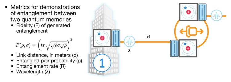 Some metrics that are important for demonstrations of entanglement between two quantum memories include:
- Fidelity. This metric defines how “good” your entanglement is. Higher fidelity will mean better quality entanglement. On a more technical level, the fidelity will tell you how closely your quantum state resembles some goal quantum state or some second quantum state. A high fidelity in that instance means the two quantum states match really well, and a low fidelity will mean that they don't match very well.
- Link distance. The goal is to achieve the largest link distances possible without affecting other parameters, as many of these parameters, or metrics, will be related to each other.
- Entangled pair probability. The probability that you will generate entanglement. The higher this is, the better.
- Entanglement rate. How often per second entanglement is generated. The higher this is, the better.
- Wavelength. This refers to the wavelength of the photon that is emitted from the stationary qubit. Remember, a stationary qubit has two energy levels corresponding to the 0 state and the 1 state. When the qubit switches between those levels, it gives off (or absorbs) a photon whose wavelength is determined by the gap between the energy levels. “Wavelength” as a qubit metric refers to which transition the quantum memory uses, because that sets the photon’s wavelength. If that native wavelength isn’t fiber-friendly, a transducer shifts it to a telecom wavelength for low-loss transmission.
The table below compares some of these metrics for entanglement established between two nodes.
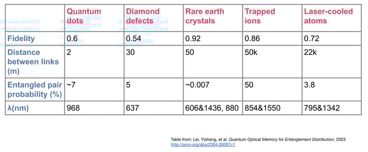 The numbers used in this table are from recent experiments. Research is still ongoing in this field, so these metrics should not be taken as fixed or final. This table gives a snapshot of the state of the art for different qubits and their properties. So from this table, we can see that there are varying fidelities that have been achieved, widely varying link distances that have been achieved, different ranges of entangled pair probabilities that have been achieved. Wavelengths that correspond to the different platforms, or different types of stationary qubits, are mostly around the visible and infrared range, but still vary widely.
––––––––––––––––––––––––––––––––––––––––––––––––––––––
What is the lifespan of a qubit? The lifespan of a qubit typically refers to the length of time a qubit can maintain its quantum state before it is destroyed by noise. In practice, this means the length of time the qubit can reliably store or process quantum information without losing coherence.
––––––––––––––––––––––––––––––––––––––––––––––––––––––
Transduction
In the Metro Area Network example, transducers are situated between the quantum memories and the fiber optic cables. What are transducers? Transducers convert photons between different wavelengths. For example, a photon with a larger wavelength may go through a transducer to become a photon with a smaller wavelength, or vice versa. Transducers are important because different parts of a quantum network may prefer different photon wavelengths. In theory, it would be simpler if every part of the system operated at one wavelength. In practice, this is not usually efficient.
To illustrate this, we can compare the attenuation values, or the amount of signal lost per kilometer, for fibers optimized at different qubit wavelengths.
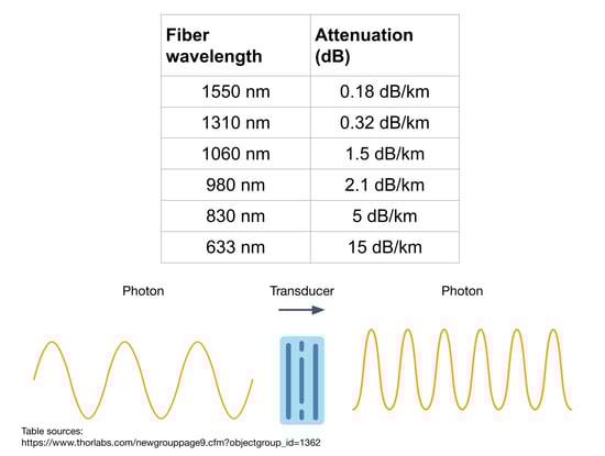 The table above summarizes those values. At 1550 nm, the attenuation is 0.18 decibels per kilometer. This is quite low. However, as wavelengths become shorter, fiber attenuation increases significantly and more of the signal is lost over the same distance. This pattern of increasing attenuation isn't random. At shorter wavelengths, tiny imperfections in the fiber cause scattering that results in fewer photons arriving at their destination. At around 1400 nanometers, there’s another issue: water molecules naturally absorb light there, creating a strong absorption band. Because of these limitations imposed by physics, only certain wavelengths in the spectrum are practical for telecommunications: around 1300 nanometers and 1550 nanometers. These are the wavelengths where fibers have the lowest loss, which is why today’s classical internet infrastructure relies on them.
The challenge for quantum networking is that quantum memories don’t naturally operate in those low-loss telecom wavelengths. Many stationary qubits in quantum memories emit and absorb photons in the 600–900 nm range. Transducers convert a photon emitted from a quantum memory at 800 nm into a telecom photon at 1550 nm capable of traveling long distances with minimal loss. At the other end of the fiber, another transducer converts the photon back into a wavelength the receiving quantum memory can use. The table below shows the wavelengths associated with different types of quantum memories.
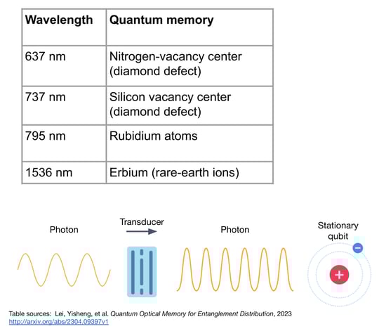 There are some quantum memories with photonic wavelengths in the telecom spectrum. For example, Erbium is a rare earth ion that operates at 1536 nanometers. This is an area of ongoing research and a promising candidate for quantum memories that are used in quantum networks.
Quantum Repeaters
Today, quantum repeaters can be broadly classified into two different types: Type I and Type II.
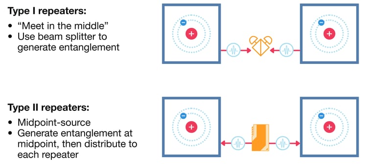 Type I repeaters, or meet-in-the-middle repeaters, use a beam splitter to generate entanglement. In this type of repeater, two quantum nodes contain quantum memories with stationary qubits. Each quantum memory emits a photon that becomes entangled with its local qubit. These two photons travel through optical fibers and meet at a beam splitter, where they undergo quantum interference. The outputs of the beam splitter are monitored by two single-photon detectors. This measurement is called a Bell state measurement (BSM). When two photons meet at a beam splitter, they can interfere in special ways. Depending on how they interfere, the photons will exit the beam splitter and be detected in particular combinations. By looking at which detectors clicked simultaneously, we can figure out whether the photons are in a specific entangled state. When the detectors do register the right coincidence pattern, it heralds the successful creation of entanglement between the two stationary qubits in the quantum memories, even though those qubits never interacted directly.
Type II repeaters are also called midpoint source repeaters. Instead of having two nodes that send photons towards some centrally located beam splitter, there is an entangled photon source located between the nodes. This entangled photon source generates photons that are already entangled, and sends one of a pair of entangled photons to each of the nodes. At each node, the incoming photon interacts with the local stationary qubit stored in a quantum memory. Through this interaction, the entanglement is transferred (or swapped) to the stationary qubits in the two distant memories. Longer chains of Type II quantum repeaters use swapping to establish longer links between nodes.
For the purposes of our example Type I (meet-in-the-middle) repeaters are used.
 How is entanglement generated in this link between Building One and the Quantum Repeater?
There is a stationary qubit in the quantum memory at Building One. It emits an entangled photon at (for example) the 600 nm wavelength. This photon is entangled with the stationary qubit in the quantum memory. This entangled photon goes through a transducer and is converted to the 1550 nm wavelength. At the Quantum Repeater, a photon at (for example) the 800 nm wavelength is entangled with the stationary qubit inside the repeater. It is emitted and goes through a transducer that converts it to 1550 nm. These photons then meet in the middle at the beam splitter and undergo quantum interference. Then, a Bell state measurement is performed. If the right kind of interference has occurred, entanglement is said to be heralded between Building One and the Quantum Repeater.
Quantum Errors
Throughout the process of generating and distributing entanglement, different types of quantum errors can occur in the quantum network. Quantum noise and quantum errors reduce the entanglement fidelity, and as a result, can reduce entanglement generation rates. There are methods for mitigating these types of errors, but some amount of noise and error is unavoidable. Quantum noise and quantum errors could come from the environment acting on the qubit. Qubits are extremely sensitive to temperature, vibration, and (if it's a solid state qubit) to material inhomogeneities.“Material inhomogeneity” is a standard technical term in quantum physics and solid-state device literature. It refers to microscopic variations in the composition, structure, or strain of a material that leads to the non-uniform behavior of qubits. Just about anything you can think of can disturb a qubit.
Visualizing Quantum Errors with the Bloch Sphere
In order to explore the types of noise that affect stationary qubits in more detail, it's useful to use a Bloch sphere diagram. The Bloch sphere is a visual way to represent qubits.
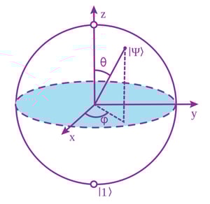
Basically, it's a globe with a radius of 1. The top of the z axis, the north pole of the globe, represents the zero state; the bottom of the z axis, the south pole of the globe, represents the one state. The Bloch sphere can represent any quantum state with a vector pointing in any direction. Points on the surface of the sphere are pure states, including superposition. Points within the sphere are mixed states, where the qubit has some randomness due to noise. For example, consider a quantum state where there is a 50% chance of measuring zero and a 50% chance of measuring one. This would be a quantum state lying somewhere on the x / y plane, along the equator of the globe. In particular, the x and y axis will represent different superposition states with different phase. In this context, the phase determines the vector on the Bloch sphere that describes the quantum state. In classical waves, phase indicates a position within one period of a wave, or the cycle of the wave: crest, trough, somewhere in between. Phase has a similar role in quantum mechanics, it describes how different parts of the qubits superposition are aligned and how the qubit behaves. When noise acts on a qubit, the state vector moves around the Bloch sphere.
Bitflip Errors
Bitflip errors have an intuitive analog in classical computing. Basically, the a bitflip error in a classical computer is when a zero becomes a one or a one becomes a zero. In the quantum world, a bitflip error is very similar: it is a 180-degree rotation on the Bloch sphere.
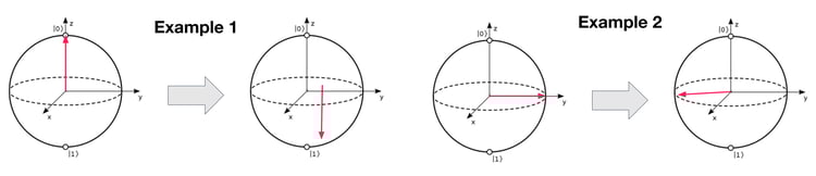 In Example 1 above, the qubit is in the zero state, but it experienced a bitflip error, and is now in the one state. This definition allows us to define bitflip errors for states where it might not be so obvious as to what state this corresponds, such as in Example 2 above. Starting in a superposition state, pointing along the y axis of this Bloch sphere, this qubit has a 50% chance of measuring zero and a 50% chance of measuring one. The bitflip error will still correspond to 180 degree rotation, resulting in the vector pointing to the left along the y axis instead of to the right on the y axis. So the phase has changed, but there is still a 50% chance of measuring zero and a 50% chance of measuring one.
Dephasing Errors
In a dephasing error, the phase becomes less known, or less defined, over time.
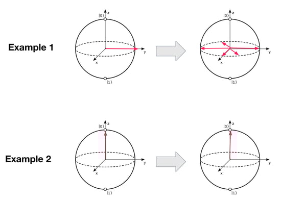 In Example 1 above, a qubit is in superposition with a 50% chance of measuring zero and a 50% chance of measuring one. If a dephasing error occurs, we no longer know where the vector lies on the Bloch sphere. We’ve represented this with several arrows pointing in different directions on the x-y plane to indicate that the phase of this qubit is uncertain. Dephasing noise does not affect qubits in their basis state: qubits in the one state or the zero state do not have phase information to lose and remain in their basis state. Dephasing noise only affects qubits that are in superposition.
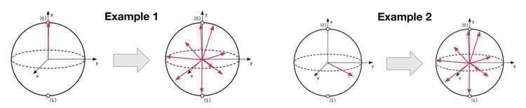
Depolarizing Errors
Depolarization is more destructive than dephasing noise. If a qubit experiences a depolarizing error, it has some probability of becoming a completely mixed state, and the vector could lie anywhere on the Bloch sphere. No matter what state the qubit is in (1, 0, or superposition), it ends up in this completely mixed state. We lose all knowledge of its direction.
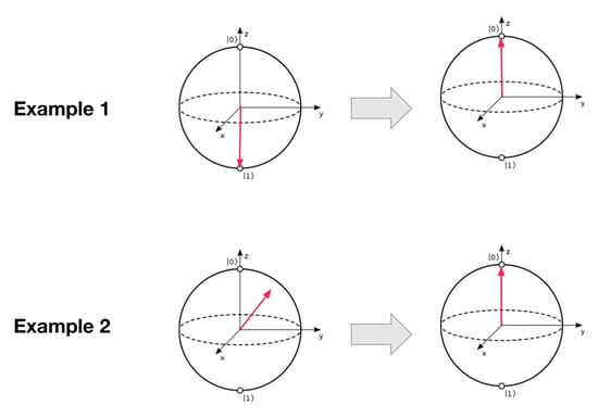
Amplitude Damping Errors
In amplitude damping errors, the qubit state always return back to the zero state. If the qubit begins in the zero state, it stays in the zero state. If the qubit begins in the one state, over time, it decays to the zero state. For a qubit in superposition, the 1 state gradually leaks away over time, leaving only the 0 portion of the state. On the Bloch sphere, this looks like the state vector being pulled to the top of the globe.
 ––––––––––––––––––––––––––––––––––––––––––––––––––––––––––––––––
What is the most common error in quantum networking? One of the major types of errors is the dephasing error because it occurs most quickly and destroys the quantum state before any other noise or errors have an impact. Some qubits are more limited by the amplitude damping error, but in most cases it is the dephasing error which is the dominant error. Protecting against dephasing is a challenge in building reliable quantum networks.
–––––––––––––––––––––––––––––––––––––––––––––––––––––––––––––––
Addressing quantum noise: Dynamical Decoupling
Dynamical decoupling is a technique to combat dephasing noise. On the Bloch sphere, dephasing can be visualized as the qubit’s state vector spreading out around the equator: instead of one sharp arrow, it looks like many arrows pointing in slightly different directions. This represents the qubit gradually losing coherence because different components of the state are drifting in phase at different rates. A bitflip operation can be performed to fix this type of noise. Recall that bitflip errors correspond to a 180-degree rotation on the Bloch sphere. If a bitflip is performed intentionally, then it's no longer an error; it’s an operation. Performing a bitflip operation will cause all of the errors that were traveling quickly in one direction to now travel quickly in the opposite direction. This causes the qubit to essentially re-phase. This is known as a spin echo technique. This doesn’t eliminate noise completely, but it cancels out predictable phase drift and can greatly extend the lifetime of qubits.
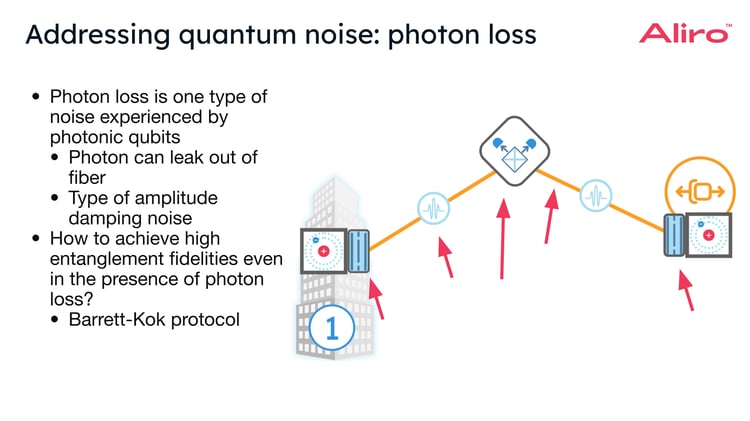
Photon Loss
Photon loss occurs when a photon doesn't end up where it's supposed to go. Mathematically, this is a type of amplitude damping noise. Given that loss exists, even on the highest quality fibers, there's still some chance a photon will be lost: they can scatter, get absorbed, or leak out of the fiber. Photon loss reduces the chances that entanglement can be successfully established between nodes. If too many photons are lost, the entanglement fidelity (quality) drops. There are protocols that mitigate these effects of loss, and help to achieve higher entanglement fidelities despite photon loss. One in particular is the Barrett-Kok protocol.
Establishing Entanglement (even with photon loss)
In the Metro Area Network link between Building One and the Quantum Repeater, each emits an entangled photon and sends it toward the beam splitter.
Along the fiber (orange line), red arrows mark places where photons can be lost.
In the middle, the beam splitter and photon detectors perform a Bell state measurement to entangle the qubits that are contained in the quantum memories at Building One and the Quantum Repeater. Techniques like the Barrett-Kok protocol can establish entanglement between two nodes, even in the presence of photon loss.
Let’s look more closely at how the Barrett-Kok protocol works.
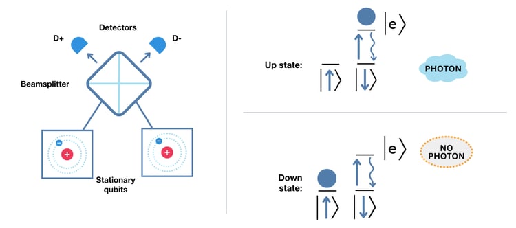 There are two stationary qubits at different nodes, and there are paths which connect them to a beam splitter, shown above in more detail with two photon detectors, which are labeled D+ and D-. The energy level for a stationary qubit consists of three states: a spin up state, a spin down state, and an excited state.
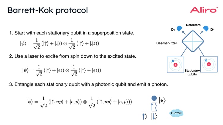
- Start in superposition. Each stationary qubit begins in a superposition of two states: spin up and spin down.
- Use a laser. A laser tuned to excite only one of those states (the spin down state) is used on the stationary qubit. If the qubit is in the spin down state, the laser excites it up to a higher excited state. From there, it quickly decays, releasing a photon. If the qubit is in the spin up state, the laser does nothing: no photon is emitted.
- The stationary qubit and the photon become entangled. If the qubit is in the spin down state, a photon is emitted; if it is in the spin up state, no photon is emitted. Since the qubit began in a superposition, the result is an entangled state of “spin up + no photon” and “spin down + photon”. In other words, the stationary qubit’s state and the photon’s presence/absence are now linked together, or entangled.
- Photon detection at the beam splitter. At this point, if entanglement was successful, the stationary qubits at Building One and the Quantum Repeater are each entangled with a photon, which they emit and send toward the beam splitter and detectors. We then wait for a detection event at the photodetectors. The goal is to have an entangled state where one stationary qubit emits a photon, but it’s not known whether it was from Building One or the Quantum Repeater. There are three possible outcomes:
-
- Both detectors click.
This means both qubits emitted photons and they exited through different ports of the beam splitter. This outcome is not useful for our purposes. We don’t want an entangled state where both qubits emitted photons. In this case, the protocol is restarted. - One detector clicks.
This is the desired outcome. A single click means at least one photon arrived, but we cannot tell which qubit emitted it. The stationary qubits are now projected into an entangled state: not perfect yet, but close to what is desired. This case can also happen if two photons were emitted but one was lost, or if both photons exited the beam splitter along the same path and hit the same detector (two photons = one “click”). Still, this is the heralded event we build on. - No detector clicks. No photons arrived (either lost in the fiber or not emitted). In this case, the protocol is restarted.
- Both detectors click.
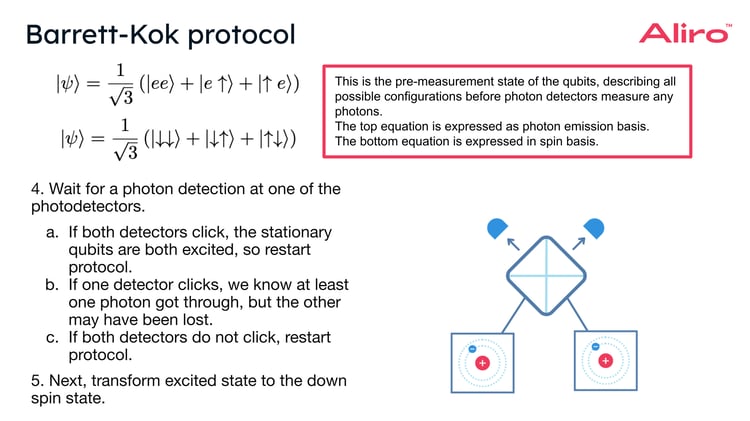
- Transform the excited state back to the spin down state. After a successful “one-click” event, the excited state is transformed back into the spin down state of the stationary qubits through local quantum operations on the stationary qubits. At this point, entanglement will exist between these two stationary qubits, Building One and the Quantum Repeater, but it will be degraded: it won't be the high-fidelity entanglement that is needed.
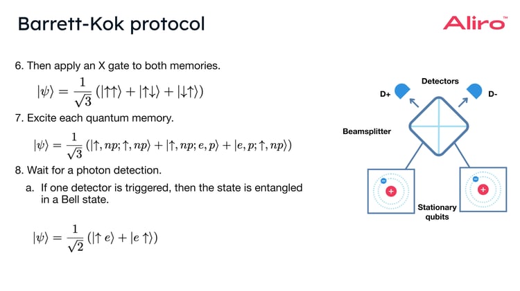
- To improve the entanglement fidelity in the Barrett-Kok protocol, an X gate is applied to each of the stationary qubits. Applying an X gate ensures that the unwanted “both excited” state is eliminated.
- This corresponds to a bitflip operation. After the X gate is applied, each quantum memory is excited via laser pulse again.
- If one detector clicks in this second round, the protocol guarantees that the two stationary qubits are now projected into a high-fidelity Bell state, meaning they are perfectly entangled.
The Barrett–Kok protocol is so useful because it’s a heralded protocol: the detectors indicate exactly when entanglement has succeeded, so failed attempts can be discarded and only successful entanglement is used to build genuine high-fidelity entangled links between distant nodes.
Final Thoughts
Qubits are one of the fundamental building blocks of quantum technologies, but their behavior is shaped by the physics of their implementation and the noise acting on them. Understanding qubit wavelengths, common errors and mitigation strategies, transduction, and entanglement protocols is essential for building scalable and reliable entanglement-based quantum networks.
The choice of qubit platform and the ability to manage errors will determine performance, efficiency, and long-term viability of a quantum network deployment. By selecting the right qubit technologies and protocols for the right applications, organizations will lay the foundation for secure, large-scale quantum communication.
A full-stack solution for Quantum Networking
Entanglement-based secure networks are being built today by a variety of organizations for a variety of use cases, benefiting organizations internally as well as providing great value to an organization’s customers. Telecommunications companies, national research labs, intelligence organizations, and systems integrators are just a few examples of the organizations Aliro is helping to leverage quantum networking.
Building entanglement-based quantum networks is no easy task. It requires:
- Emerging hardware components necessary to build the quantum network
- The software necessary to design, simulate, run, and manage the quantum network
- A team with expertise in quantum physics and classical networking
- Years of hard work and development
This may seem overwhelming, but Aliro is uniquely positioned to help you build your quantum network. The steps you can take to ensure your organization is meeting the challenges and leveraging the benefits of the quantum revolution are part of a clear, unified solution already at work in quantum networks like the EPB Quantum Network℠ in Chattanooga, Tennessee.
AliroNet™, the world’s first full-stack entanglement-based quantum network solution, consists of the software and services necessary to ensure customers will fully meet their quantum networking goals. Each component within AliroNet™ is built from the ground up to be compatible and optimal with quantum networks of any scale and architecture. AliroNet™ is used to simulate, design, run, and manage quantum networks as well as test, verify, and optimize quantum hardware for network performance. AliroNet™ leverages the expertise of Aliro personnel in order to ensure that customers get the most value out of the software and their investment.
Depending on where customers are in their quantum networking journeys, AliroNet™ is available in three modes that create a clear path toward building full-scale entanglement-based secure networks: (1) Emulation Mode, for emulating, designing, and validating quantum networks, (2) Pilot Mode for implementing a small-scale quantum network testbed, and (3) Deployment Mode for scaling quantum networks and integrating end-to-end applications.
AliroNet™ has been developed by a team of world-class experts in quantum physics and classical networking.
To get started (or continue on your quantum journey), reach out to the Aliro team for additional information on how AliroNet™ can enable your quantum network.
References
"Bloch sphere." Wikipedia, Wikimedia Foundation, 28 Sept. 2024, en.wikipedia.org/wiki/Bloch_sphere
"Flawed Diamonds Can Be Used to Interface with Quantum Computers." Phys.org, 9 Dec. 2021, phys.org/news/2021-12-flawed-diamonds-interface-quantum.html
Lei, Yisheng, et al. "Quantum Optical Memory for Entanglement Distribution." arXiv, 18 Apr. 2023, arxiv.org/abs/2304.09397v1
"Photon Storage in a Ground-State Vapor Cell for Quantum Memory." Tech Explorist, 30 June 2023, www.techexplorist.com/photon-storage-ground-state-vapor-cell-quantum-memory/52091/
"Polarization of Light." RP Photonics Encyclopedia, www.rp-photonics.com/polarization_of_light.html
Rijsman, Bruno. How to Integrate a Quantum Network with Your Existing Network. Aliro Technologies, 2023. BrightTALK, www.brighttalk.com/webcast/19861/578474
"SMF-28 Ultra Optical Fiber Specifications." Thorlabs, https://www.thorlabs.com/newgrouppage9.cfm?objectgroup_id=1362