
PRACTICAL FIELD DEPLOYMENT
Stabilizing Quantum Links in Quantum Networks
Considerations for a secure, robust quantum network deployment.
Summary
Quantum Secure Communication (QSC) is the highest level of security possible today, but real-world deployments of quantum networks to support QSC (and QKD) require more than a functional protocol. This white paper explains how quantum information is encoded on photons, how entanglement-based QKD / QSC operates over fiber networks, and what is needed to make it practical in the field. Practical considerations include link stabilization, timing and polarization synchronization, automation software, and the foundations for a secure, robust quantum network deployment.
Introduction
As organizations prepare for the quantum era and look to build quantum networks to secure their communications, attention has largely focused on upgrading algorithms and key management systems. Yet one of the most powerful tools for long-term secure communication, entanglement-based Quantum Secure Communications, poses a different kind of challenge: how can fragile quantum protocols that work well in a controlled lab environment be run reliably, automatically, and securely over real-world network environments that are noisy and dynamic?
This white paper addresses that challenge from an engineering perspective. We begin by reviewing how quantum information is encoded on individual photons using practical degrees of freedom such as time, frequency, and polarization, and how entanglement-based protocols like BBM92 use these encodings to establish intrinsically secure keys between distant users. We then turn to the realities of deployed infrastructure: underground and aerial optical fibers, undersea links, and free-space channels are all subject to temperature changes, vibrations, background light, and other factors that continuously interfere with timing, polarization, and signal quality.
Building on field studies and experimental demonstrations, concrete techniques for stabilizing these quantum links are explored, with a focus on timing synchronization, polarization control, and noise mitigation. We examine how classical references and quantum signals can each be used for feedback and compensation, and how automation, network management software, implementation security, and physical packaging must work together so that entanglement-based cryptography can operate as a robust, largely hands-off component of modern communication infrastructure.
Encoding Quantum Information in Photons
Degrees of Freedom
What does it mean for quantum information to be encoded in light, or in an electromagnetic wave? These fields can be described using degrees of freedom: the different independent ways a photon (or light field) can carry information or be changed. Degrees of freedom include time, frequency, spatial, polarization, as well as amplitude and phase. 
Each of these degrees of freedom is like a knob you can turn to encode, manipulate, and measure quantum information. For instance, the time of arrival of photons forms the basis for time-bin encoding. The frequency of a photon, or color, defines another degree of freedom used for encoding states, as well as for routing and multiplexing. The spatial degree of freedom, of any field can be, something as simple as a Gaussian beam in single mode fiber, or it can be more complex and can carry out vital angular momentum modes. Polarization, which is described by the orientation of the photon's electric field, is widely used as a degree of freedom in quantum information for encoding quantum states. Amplitude and phase are redefined in the single-photon regime as complex probability amplitudes, which describe where and how a photon is likely to be detected. This would be with respect to the other degrees of freedom.
Single-Rail, Dual-Rail, and Multi-Rail Encodings
Let's now look at how quantum states are encoded in a photon. This is typically described in terms of single-rail, dual-rail, or multi-rail encoding.
In the case of single-rail encoding, the logical state is represented by the presence or absence of a photon and this corresponds to the |0⟩ and |1⟩ states. A superposition of these states is also possible, and this represents a generic qubit. This can also be generalized to qudits, which have higher dimensions (more than two levels) compared to qubits. For qudits, higher photon-number states involving more than one photon are used. In this case, the photons occupy a single optical mode, while multiple photon-number (Fock) states within the same optical mode can be used to encode a qudit. The optical mode in single-rail encoding can be defined by for example, a single time bin, a frequency channel, a polarization, or a spatial mode.

In dual- and multi-rail encoding of a qubit or qudit onto a single photon, the quantum state is encoded onto two (or more) orthogonal optical modes corresponding to different photonic degrees of freedom. For example, a photon in a superposition of two distinct polarization modes or two distinct time bins forms a qubit, while superpositions over three or more orthogonal modes form a qudit. This is referred to as dual- or multi-rail encoding of a photon.
More generally, photonic quantum states can be superpositions of both different photon-number states and different orthogonal optical modes.
Practical Encodings for Single-Mode Fiber
The combination of how a qubit is encoded (single-rail vs. dual- or multi-rail encoding) and the degree of freedom used (time-bin, frequency-bin, polarization, path, orbital angular momentum) to encode the information impart different characteristics to the qubit. Some types of qubits are more relevant to fiber optic communications.
Among these encodings, the time-bin, frequency- bin, and polarization are the most practical for transmission through single mode fiber. This is important because single mode fiber is the backbone of today's telecommunications networks, and light in single mode fiber is confined to a single spatial mode. As a result, spatial encodings such as orbital angular momentum, and large-scale path encoding over separate fibers, are not naturally supported by existing infrastructure and are more challenging to deploy over long distances. These encodings are more easily and reliably implemented on integrated photonic or free-space platforms rather than across long distance fiber links. Each encoding type has unique advantages and sensitivities. Understanding how they interact with the noise is also an important consideration to take into account.
Entanglement-Based QKD (BBM92): the Basics
Now that we have set some foundations around encoding quantum information, let's briefly look at the quantum key distribution protocol BBM92. This is one of the entanglement-based quantum key distribution protocols, amongst others like Ekert91 and measurement-device independent QKD (MDI-QKD). In BBM92, an entangled photon source generates pairs of photons that share strong correlations in a specific degree of freedom, such as polarization or time-bin. Each photon is then sent from the source node to two users; in examples, these users are often named Alice and Bob. These two end nodes (Alice and Bob) measure their photons using a randomly chosen basis. By making these measurements and comparing the basis choices, they can extract the outcome of their measurements and use the perfect correlations that are present to form a secret key that is shared between them.

–––––––––––––––––––
This is the foundation of entanglement-based cryptography. For more detail about the BBM92 protocol, please see our other webinars on BrightTalk.
–––––––––––––––––––
What is required to make quantum protocols like BBM92 reliable and practical in real-world fiber networks?

Stabilization of the link. The links that carry photons are not static. Link properties can change over the course of the day due to temperature fluctuations, mechanical stress, or other environmental factors. These changes in the fiber may cause polarization to rotate, arrival times to vary, and noise to creep into the signal. In order to maintain reliable communication, these effects must be actively compensated for.
Automation. Stabilization routines, calibration and network starter procedures ideally run without operator intervention over long periods of time so that the network can continue to operate without constant human mediation.
Implementation security. When it comes to quantum network hardware implementation, there can sometimes be imperfections that will introduce vulnerabilities. Calibration of these imperfections and countermeasures that safeguard against side-channel attacks will be essential to any robust deployment.
Packaging and deployment of quantum nodes. Packaging is an important consideration, depending on the application and whether the nodes need to be portable, or designed to withstand environmental extremes such as large temperature swings or radiation. The design and packaging of the system should protect the nodes from these environmental factors while also staying within constraints on size, weight, power and cost.
Environmental Impacts on Quantum Links
Leveraging existing telecom fiber infrastructure is the most efficient way to scale quantum networks. In urban areas, these optical fibers are typically underground or aerial installations paired with an overhead power line. Many intercontinental fiber connections are made using undersea fiber optic cable. In addition to these fiber optic connections, free-space and ground-to-satellite channels are also crucial for long distance connectivity.
As photons travel through these various channels, their properties, such as polarization, timing, and phase can all fluctuate and introduce noise into the received signal. The severity of these effects depends on whether the fiber is buried or aerial, and the environmental conditions under which the fiber or free-space channel is deployed.

Free-space Links and Ground-to-Satellite Links
Free-space links and ground to satellite links are extremely sensitive to environmental factors that introduce rapid fluctuations. Maintaining good signal quality in these links often requires adaptive optics, careful alignment, and other stabilizing measures.

Some environmental factors that impact free-space and ground-to-satellite links include turbulent temperature gradients, which can distort the beam and cause beam wandering, where the angle of the beam varies over time, reducing signal quality and coupling efficiency. Weather effects, such as fog, rain and snow, reduce the transmission. In addition to this, daytime operation becomes a problem, with noise pollution from the sunlight being introduced into the signal.
________________
We've covered some of these effects in previous webinars in greater detail. Please refer to the webinars on satellite based quantum communication for more:
- Quantum Networking with Satellites
- Satellite Quantum Communication: Topologies, Demonstrations, and Design Considerations
________________
Fiber Optic Links
Aerial fiber optic cable, which is frequently installed below power lines on shared utility poles, are highly exposed to the environment: wind, rain, ice, and even bird activity. These factors can disturb the fiber mechanically and affect polarization, timing, and other qubit characteristics. In underground fibers, the conditions are more protected from direct environmental effects, although temperature variations and ground vibrations will still introduce drifts. Underwater fiber optic cables are comparatively more stable, with some deep sea segments being largely immune to daily or seasonal environmental fluctuations. These undersea cables create a system and deployment scheme for intercontinental quantum links moving forward.

Temperature fluctuations and mechanical vibration are the main causes for drift in fiber optic quantum network deployments. With respect to temperature fluctuations, these can occur because of daily cycles or seasonal changes. These changes alter the refractive index and effective fiber length, which can also be polarization dependent. These changes thereby affect the timing, phase, and polarization of the photon. Mechanical disturbances are equally important. Vibrations from human activity could be present, street traffic, or seismic events can disturb the fiber.
In fact, the high sensitivity of fibers to these factors also allows them to serve as sensors in some applications, where detecting mechanical disturbance and temperature variation is of special interest.
Case Study: Characterizing a 14 km Urban Fiber Link
To see these effects in practice, consider this study of a 14 kilometer dark fiber link in Saarbrucken, Germany, connecting Saarland University and the University of Applied Sciences.

The link is partially underground and partially aerial. The study characterized time-dependent drifts in the fiber links and was intended for both classical and quantum channels in their experiments, helping us understand how environmental disturbances affect these different degrees of freedom, photon loss, and more. The experimental setup: one of the photons from an entangled pair that is generated at the first node is detected locally while the other is converted to the telecom band, and it is sent through the urban fiber link.
During quantum experiments, detected signal at the second node is encoded on an optical pulse and sent back to the first node so that time tagging of both the photon detections can be performed in the same node. The setup figure is included below.
The characterization experiments involved a classical signal that traverses the full fiber loop connecting the Quantum link (Link-Q) and Classical (Link-C) fibers
The drift in the link and the fiber’s influence on photon timing, polarization, and other properties are studied in detail.

What were the observations with regards to timing fluctuations?

Interferometric transmission time measurements were performed, where a classical auxiliary laser signal was sent through the fiber, its frequency was slightly shifted at the end node using an acousto-optical modulator, and the light was looped back and interfered with a local reference signal to recover arrival-time differences. The resulting beat signal was analyzed to monitor changes in the optical path length of the fiber over multiple days. A change in the optical path length induces a phase shift and, if time-dependent, a Doppler shift in the detected beat frequency, enabling precise tracking of arrival-time drifts. The results of this study show a strong correlation between temperature fluctuations and photon arrival time. The fiber’s refractive index is temperature-dependent, which changes the effective optical path length and, in turn, the effective speed of light in the fiber. This leads to the observed drift in arrival times, or delay.
Polarization measurements were also conducted as part of this study.
In this case, two fixed-reference polarizations were sent as inputs and were alternated periodically. By measuring the output polarization, the rotation matrix that is introduced by the fiber, and corresponding parameters that describe this rotation matrix, known as Stokes parameters, are plotted. This measurement is performed over several days.

The results pictured above show polarization fluctuations are visibly stronger during daytime than at nighttime. This is likely due to increased human activity, and potentially some temperature fluctuations. These results illustrate the need for faster compensation during daytime operation, in regard for deploying networks.
Another factor in quantum networks is loss, specifically polarization dependent loss, or what is termed PDL in this study. In fiber, two orthogonal polarizations, typically horizontal and vertical, can experience different losses as they propagate. This difference in loss reduces the fidelity of the quantum state received at the end node.
Pictured below are results from this study regarding the polarization dependent loss measured over time.

The average value was used to estimate the expected fidelity of the transmitted state, and it was found to be around 99% and greater, which is excellent for QKD / QSC applications. At this level, the effect of polarization dependent loss can essentially be ignored. The extent of the effect is very link specific, however, and it also depends on link distance. So link characterization does play a crucial role in determining which metrics have a stronger impact on the link, and helps to inform which compensation techniques are necessary, if they are necessary at all.
Another source of disturbance is light pollution and background noise. The classical signals in adjacent fibers have been found to be a major source of leakage to the quantum channel, reducing the fidelity and signal visibility.

In this study, two measurements were made. The first plot pictured above shows the effect of classical signals traveling in nearby fibers. Some crosstalk occurs, which leads to leakage of light into the quantum channel. The plot indicates high noise levels around 10 to the power of 4 background counts per second. This noise does not strongly depend on the time of the day, and it has been attributed to activity at the patch stations or data traffic in the nearby fiber. The second plot pictured above demonstrates the effect of applying spectral filtering by blocking wavelengths outside of the quantum signal wavelength band.
Filtering reduces background noise. The crosstalk and the noise levels are lower when the filter is used, and it helps maintain a high signal-to-noise ratio.
In another example, this can be seen more clearly by considering measurements of the noise levels as a function of wavelength as pictured below.

Characterizing the noise as a function of the wavelengths helps determine the requirements of spectral filtering. These measurements help guide which frequency bands to reject, ensuring that any photons that are not in the desired band in the quantum channel are suppressed, so a high signal-to-noise ratio can be achieved.
Timing Synchronization in Entanglement-Based Networks
Timing synchronization is essential in entanglement-based networks because end nodes must correctly match detection events that originate from the same entangled photon pair. Although the photons travel different path lengths and arrive at different times, their detection times remain strongly correlated. By time-tagging events and aligning the two nodes’ time bases (accounting for clock drift and path-delay variations), the system can identify true coincidences within a defined coincidence window and reject accidental coincidences from background counts.
Approaches to Timing Synchronization
Timing synchronization is an evolving field, and new techniques continue to emerge. The images below show three different approaches:
- a White rabbit precision time protocol,
- a classical sync pulse based on detection signal from one node time multiplexed with quantum signal routed to the other node, and
GPS clocks and a coincidence histogram for timing drift compensation.
Pictured above is a rubidium clock at the source node being used to distribute 10 MHz clock reference using a classical optical signal to both the remote nodes. This uses White Rabbit timing references, where White Rabbit is a protocol that was developed at CERN to provide sub-nanosecond synchronization. It combines the precision time protocol with physical layer clock recovery and phase tracking, allowing highly accurate distribution of clock reference. The classical reference that was used shares the same fiber with the quantum signals. This is achieved with wavelength division multiplexing, where the two signals, classical and quantum, occupy different wavelength bands. This was tested across a distance of 100 km, using 50 km spools going from the source node to the two end nodes.

At the end nodes, the classical reference is used to tag the arrival of the photon. This enables precise coincidence measurements over distances. In examples like this one, an important consideration is eliminating the crosstalk that can occur from the classical reference to the quantum signal. The classical signal wavelength is chosen to minimize noise from Raman scattering that pollutes the quantum signal. What can be noted from this example is that the drifts in the classical reference and the quantum signal going through the same fiber ensures synchronization at the two nodes. For example, if this was done over different fibers and those two fibers impart different drifts over time, this wouldn't be as successful.
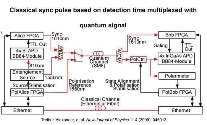
In another approach, shown in the figure above, detection at one node was used to generate classical optical pulses that then travel along the same fiber as the quantum signal, through time multiplexing. At the receiving node, the classical pulse that was sent from the first node is used to gate the detector – to open the detector for photon detections for precise time windows. As these two quantum and classical signals travel the same fiber length, this automatically accounts for the drift in the link and the detectors will be timed to be opened for accepting the photons and the coincidence detections will have accurate time tags.
In another example, pictured below, GPS clocks were used as global time reference. For long links, fiber-introduced drifts need to be accounted for.
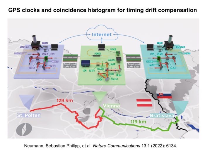
This demonstration was conducted over a distance of 248 km between the end nodes (St. Polten and Bratislava) . The source node (in Vienna) is situated between the two end nodes. In this network, the drift is compensated for by monitoring coincidences of entangled photons and histogramming the arrival time differences at the two end nodes to determine the timing offset. This is repeated to account for the timing drifts in the links and correct the offset of the reference, which is originally based on GPS clocks.
Each of these approaches to timing synchronization have unique benefits and tradeoffs depending on link loss, speed of link drifts, and thus choosing a particular approach is dependent on the link characteristics and the downtime for drift compensation that can be tolerated in a specific application.
Further Considerations for Timing Synchronization
Further considerations for synchronizing two non-local remote nodes include the level of precision that is required, which depends on which degree of freedom is used for encoding and the application the network is being used for. For example, when using frequency encoding, the timing requirements can be extremely tight. In such cases, the requirement is for tens of gigahertz scale radio frequency signals to be distributed, and the jitter would need to be a few orders smaller than the RF period. The requirements are oftentimes sub-picosecond timing precision, for tens of GHz qubit bandwidths to maintain high fidelity for the desired quantum state. .
In the case of polarization and time-bin encoding, the synchronization precision needed is typically less extreme (ranging from one nanosecond to a few picoseconds), but still tied to source bandwidth and detector jitter.
The application plays a vital role in the jitter requirement. For example, sensing applications that aim to measure the time of flight difference between the photons can utilize detectors with low jitter (in the picosecond scale) and a source with large bandwidth resulting in correlation width ideally lower than detection jitter. This will impose timing synchronization precision in the picosecond scale as well.
Other practical factors that influence which timing synchronization approach should be utilized is how fast photons are being generated and sent down the link. Lower photon rate implies that synchronization applied using the coincidence histogram will update slowly. Link distance and loss are important considerations, and determine how many of the many photon pairs generated actually reach the intended nodes.
Timing jitter from the link itself is another notable consideration as it impacts the drift caused by temperature fluctuations and other environmental factors. The faster this drift occurs, the faster the synchronization updates need to be.
Taking all of these considerations into account, if there are enough correlated photon pairs that reach the end nodes to allow for the quantum signal itself to be used for synchronization, this is a great choice. Using the quantum signal itself can reduce the amount of additional hardware that might be needed. On the other hand, a classical reference could be used, either in a separate fiber or the same fiber, depending on the level of drift that is expected and whether the drift is repeatable in another fiber. When a reference that shares the same fiber with the quantum signal is used, the coexisting classical-quantum signal choice helps ensure that the drifts seen by the classical reference is identical to that seen by quantum signal, thus compensating for one, corrects the drift in the other as well. The choice of timing synchronization methodology depends on how fast the drifts occur in the link. Links with slower drift may benefit from using the quantum signal itself for synchronization, rather than relying on a classical reference. Classical reference signals enable higher power levels and faster correction rates, while quantum-based synchronization can be limited by photon flux which limits the correction rates, especially for longer link distances and higher fiber losses.
Polarization Stabilization and Drift Compensation
Another link parameter that can drift over time is polarization. If a polarization encoded qubit changes or degrades in transit, quantum performance suffers: the entangled state that reaches the end node is of a lower fidelity, and the Quantum Bit Error Rate (QBER), a metric that is often used for key distribution, increases.

In practice, there are two main approaches to compensating for polarization drifts: classical reference-based compensation and quantum signal-based compensation.
In classical reference-based compensation, a classical optical signal is transmitted alongside the quantum channel that allows for fast drift characterization and correction. This has similar tradeoffs to a classical sync pulse used for timing synchronization, as discussed previously. This method requires dedicated hardware, such as polarimeters.
In the case of quantum signal–based correction, the system estimates and corrects polarization drift using the quantum signals themselves. This reduces hardware requirements; however, the photon generation and detection rates must be sufficiently high to accurately estimate the drift and keep the applied corrections updated, particularly if the drift dynamics are fast.
If the environment induces rapid polarization fluctuations in the link, requiring very fast tracking, and the application demands minimal downtime for drift compensation, a classical reference–based method is often the better choice. If the priority is simpler hardware and the system can support the required photon generation and detection rates, quantum signal–based compensation can be an attractive alternative.
Quantum Signal-based Polarization Compensation
Quantum Bit Error Rate (QBER) is a measure of the rate of disagreement between the end nodes’ raw keys. If no eavesdropper is present, changes in QBER can be used to infer polarization drift in the link. As the QBER rises, that increase can be used to guide an optimization loop that restores polarization alignment. If an eavesdropper is present, this optimization loop would not correct the QBER to an acceptable level, so using this method does not prevent eavesdropper detection.
In one example, researchers in Singapore evaluated polarization drift in a 10 km underground fiber link in a loop configuration.
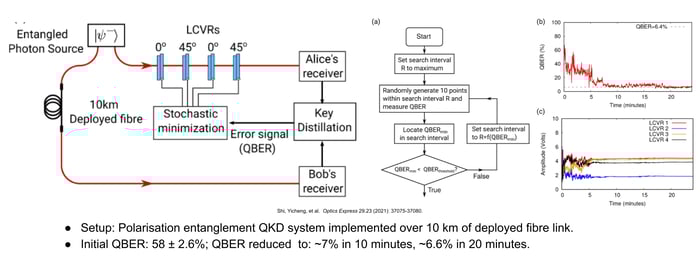
The polarization compensation used the QBER as the feedback signal: :a blind search algorithm, in which the bit error rate was used as feedback, determined which adjustments to apply to achieve optimal correction. In this particular example, it took about 10 to 20 minutes to achieve an effective correction.
Another example of using QBER for polarization compensation used a longer link distance of 248 km between the two end nodes.
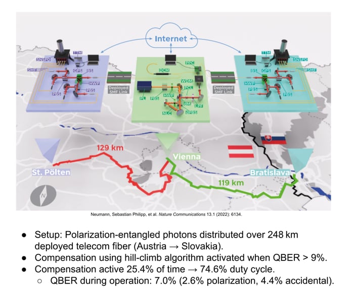
The source node here was located in Vienna, and the end nodes were in St. Polten and Bratislava. In this example, the polarization compensation took a significant portion of the total operational time, close to 25%. The compensation in this case was triggered only if the QBER exceeded a threshold.
Using QBER threshold as a trigger is a popular method in error correction in key distribution protocols, because the security of the protocol depends on maintaining QBER below a particular threshold. As long as QBER stays within these defined bounds, the system can perform effective error correction and authentication while maintaining a positive secure key rate after post-processing.
In this example, once the QBER exceeded a threshold of 9%, the compensation routine was triggered and it was used to reduce the QBER metric and bring it down to an acceptable operating range. To achieve this, the study relied on a hill-climb algorithm.
These examples highlight that the choice of compensation strategy affects the amount of time the system has to dedicate to key generation versus stabilization. This is largely dependent on the link loss, link distance, and the pair generation rate. The choice of hardware controllers and polarization compensation approach must take these constraints into account in order to meet the link’s stability and key-rate requirements.
Classical Reference–based Polarization Compensation
Classical reference–based polarization compensation stabilizes the quantum channel by sending a co-propagating classical optical reference and using it to continuously track polarization drift and drive real-time corrections.
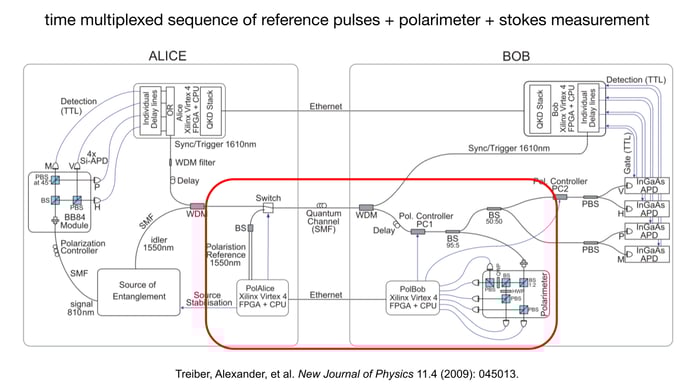
In one example, the experiment was conducted in a laboratory setting using a 25 km spool. The red box in the image above contains the polarization compensation hardware, including a switch that is used to choose between using the quantum signal or the classical reference for polarization compensation.
The reference signal is in the same wavelength band as the quantum signal, and the two are time-multiplexed. The system alternates between sending quantum states for key generation and sending a reference burst consisting of two predefined polarization states, which are used to probe the link’s current polarization transformation.
At the end node (Bob) a fraction of the classical reference signal is routed to a polarimeter. The single photon detectors are deactivated when polarization compensation is active, as the detectors need a gate voltage to be enabled. The polarimeter measures the Stokes parameters, and by comparing the known transmitted reference states to the measured received states, Bob can determine the unitary transformation that has occurred, and apply the appropriate correction to compensate for the drift in the link.
The figure below illustrates measurements of entangled photon visibility over run time without and with the polarization compensation being used.
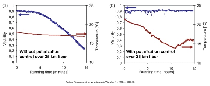
The second plot shows the visibility (in blue) is very stable with polarization control applied, despite huge temperature fluctuations. In the first plot, there is a degradation in the visibility (in blue) over time when there is absence of compensation.
Another example of polarization compensation was demonstrated by Qunnect, a quantum hardware company, using 34 km of buried optical fiber in New York City. Time-multiplexed polarization references were generated and sent using a polarizer and a polarization controller, to periodically probe the link and support polarization drift compensation.
As in the previous example, a switching mechanism alternates the quantum signal and classical signal transmission. At the end node, a polarimeter makes measurements of the classical signal to determine the Stokes parameters. These measurements are then used with a gradient-descent algorithm to compute and apply the appropriate polarization controller settings to compensate for polarization drift in the fiber.
Oftentimes, the classical-based polarization reference is chosen to be in the same wavelength band as the quantum signal. This helps to ensure that the reference signal experiences (as closely as possible) the same polarization evolution as the quantum channel, so the correction derived from the reference can be applied effectively to the quantum states.
If the classical reference is very different in wavelength, the reference and quantum signals may drift differently. Approaches that use a reference at a substantially different wavelength are being studied and explored, but they generally require extra care to account for these wavelength-dependent effects.
Automation and Network Management Software
Once timing synchronization and polarization drift are addressed, integrating these routines into a coordinated, automated workflow is the next step in building and scaling reliable quantum networks.
When starting the link, such as a link dedicated to quantum key generation, if the link hasn't been active for a while, it needs to run a start-up routine. Typically this begins with timing synchronization so coincidence windows can be aligned. Then the system may run source and setup stabilization, for example: if the photon coupling needs to be stabilized over time. Then polarization compensation is executed so the desired QBER can be achieved in the secure key generation protocol.

Network management software plays an important role. It continually monitors the essential health metrics, such as timing offsets and QBER, and determines which routine needs to be triggered over time as drift accumulates. A useful way to think of this is like a state machine, where the software continually evaluates which operation needs to be implemented to keep the link operating at optimal performance.
This kind of a hands-off orchestration is critical for real-world continuous Quantum Secure Communication. It allows the network to operate reliably without constant manual intervention.
Implementation Security
Secure operation of a quantum network also requires addressing implementation security. Even if the link is perfectly stabilized, hardware imperfections can introduce vulnerabilities which could make the link susceptible to side channel attacks.
For example, these imperfections could be differences in detector efficiencies or slight timing offsets in basis measurement. These differences could be exploited by an eavesdropper. Calibration routines and corrective measures are needed in order to mitigate these risks. A hardware protection layer, such as spectral filters or power fuses, can help prevent strong light pulses from being injected by the eavesdropper intending to damage sensitive detectors or influence the measurements. These precautions form an essential part of implementation security, ensuring that the system that is deployed is resilient against both accidental errors that could occur and intentional side channel attacks.
Packaging Quantum Nodes
Another important aspect of quantum network deployment is the physical packaging of the end nodes. Quantum systems often include delicate optics, photons sources, and even cryogenic detectors – all of which must remain stable under operating conditions. While designing these end nodes, it is important to consider the SWaP-C constraints of size, weight, power, and cost, especially for a system that is intended to integrate into a rack-mounted solution or will be deployed in an environment with large thermal fluctuations.
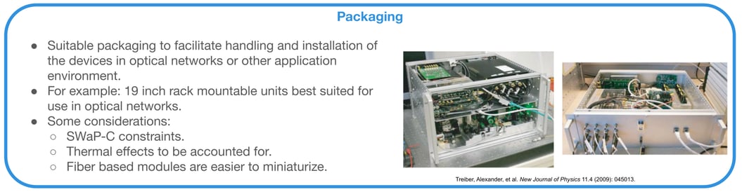
The specific considerations of the application in which the nodes would be deployed must be considered as well. Proper packaging enables long-term network operation that is reliable, and can run with the necessary stabilization and compensation routines in place.
Closing
Environmental noise is unavoidable, and it can affect the performance of quantum networks. In order to achieve effective and efficient operations, robust stabilization routines for both timing and polarization must be considered. In practice, this depends on integration of quantum optics, classical optical hardware, and software control systems. All of these elements come together in order to ensure that the network can operate reliably in real-world deployment environments.
A Full-stack Solution for Quantum Networking
Entanglement-based secure networks are being built today by a variety of organizations for a variety of use cases, benefiting organizations internally as well as providing great value to an organization’s customers.
Telecommunications companies, national research labs, intelligence organizations, and systems integrators are just a few examples of the organizations Aliro is helping to leverage quantum networking. Building entanglement-based quantum networks is no easy task. It requires:
- Emerging hardware components necessary to build the quantum network
- The software necessary to design, simulate, run, and manage the quantum network
- A team with expertise in quantum physics and classical networking
- Years of hard work and development
This may seem overwhelming, but Aliro is uniquely positioned to help you build your quantum network. The steps you can take to ensure your organization is meeting the challenges and leveraging the benefits of the quantum revolution are part of a clear, unified solution already at work in quantum networks like the EPB Quantum Network℠ in Chattanooga, Tennessee.
AliroNet™, the world’s first full-stack entanglement-based quantum network solution, consists of the software and services necessary to ensure customers will fully meet their quantum networking goals. Each component within AliroNet™ is built from the ground up to be compatible and optimal with quantum networks of any scale and architecture. AliroNet™ is used to simulate, design, run, and manage quantum networks as well as test, verify, and optimize quantum hardware for network performance. AliroNet™ leverages the expertise of Aliro personnel in order to ensure that customers get the most value out of the software and their investment.
Depending on where customers are in their quantum networking journeys, AliroNet™ is available in three modes that create a clear path toward building full-scale entanglement-based secure networks: (1) Emulation Mode, for emulating, designing, and validating quantum networks, (2) Pilot Mode for implementing a small-scale quantum network testbed, and (3) Deployment Mode for scaling quantum networks and integrating end-to-end applications.
AliroNet™ has been developed by a team of world-class experts in quantum physics and classical networking.
To get started (or continue on your quantum journey), reach out to the Aliro team for additional information on how AliroNet™ can enable your quantum network.
Frequently Asked Questions
Could an attacker exploit timing synchronization channels to inject false signals or infer key material? Does timing information itself leak usable side channel data?
This is an important question. Timing channels together with specific hardware imperfections are, in fact, a potential side channel. What this means is that side channel attacks can happen if an attacker has access to the classical synchronization signal and is able to leverage any residual hardware imperfection. For example, the optical burst pulses or white rabbit references discussed in this white paper could be hijacked by bad actors to inject false timing data and manipulate detector gating to gain information by leveraging any residual offsets in the detector response times. In combination with hardware imperfections, they could infer photon arrival patterns via side-channel attacks.. It is important to consider how these classical reference signals and channels are secured; these channels must be authenticated to protect timing references from manipulation along with implementing countermeasures for hardware imperfections that can lead to side channel attacks.
Can environmental effects be modeled predictively rather than reactively, allowing feed forward correction of phase drift?
This is not entirely possible because perturbations in fiber optic cable are highly stochastic. However, it is possible to have some sensors along the fiber in the nodes in order to monitor temperature fluctuations and anticipate where drifts would occur or not.. However, because this is a probabilistic, stochastic process and the perturbations can occur in a random manner, it’s important to have a reactive kind of feedback that is sufficiently fast to keep up with the drifts.
How does synchronization scale in a multi-node quantum network? Does each pair of nodes synchronize independently or through a shared master clock?
There are a couple of ways to perform synchronization. We've discussed one very popular method, where there is a central master clock that shares the reference to all the other end nodes. This would be something like a star topology. One could also perform pairwise synchronization where two nodes at a time perform synchronization with each other. Usually the master clock-based approach leads to a simpler network-wide timing distribution. Pairwise synchronization could be preferred depending on the network topology (chain network) and if the application demands for the same.
The answer here mostly depends on the topology and application.
What happens if one node drifts while the others remain stable? Is that something that can happen, and can the network correct that locally? Does it need to be a global re-synch? How does that affect your network?
The local node receives information from the other nodes regarding detection time tags and basis. This allows it to, build a histogram of photon detection time differences and determine the timing offset at which coincidences occur and whether this offset has changed.
Thus, in an entanglement-based system, the quantum signals used for key distribution rely on time tag information from other nodes to generate coincidence outputs. By comparing the time tags between two nodes, the system can determine whether an event is a coincidence. If the coincidence timing offset drifts, metric such as the total key rate would drop. Such a drop can indicate that a link or node has experienced a timing offset, which can be confirmed by building a coincidence histogram.
After this, correction can occur locally, meaning that the hardware at the affected node performs the adjustment. However, this correction depends on communication with the other participating nodes to determine whether a correction is needed and what it should be. In other words, the process combines feedback from other nodes with local hardware action to maintain synchronization.
Does synchronization get harder when using different kinds of encoding? So if you're using time bin encoding or polarization or frequency encoding. How does that complicate your synchronization?
Yes, it does. Take the example of frequency-bin encoding: the unitary operations that are performed for frequency-bin–encoded systems use a modulator. How does the modulator perform this operation? It uses an RF sinusoidal signal that mixes the different frequency components present in the system with each other. That is how the unitary transformation can be achieved.
In order to really allow interference between these different frequency components, the RF waveform used to modulate them needs to be at a frequency equal to the frequency-bin separation, and the timing jitter needs to be much lower (by multiple orders) than the total inverse bandwidth of the qubits/qudits to allow for stable interference of frequencies across the total bandwidth with high fidelity. In other words, the requirements on timing jitter depend on the bandwidth of the frequency-bin–encoded system.
Usually, the frequency bin systems require frequency bin spacing at least a few gigahertz so that the adjacent frequency bins do not overlap and this is limited by the minimum achievable frequency bin width by interferometers and etalons used to generate these states. The inverse bandwidth will be on the order of tens to hundreds of picoseconds, but to achieve high fidelity of the applied unitary transformation, the timing jitter in the RF waveform needs to be sub-picosecond—much lower than the inverse bandwidth. Timing precision at the 0.5 ps to 0.1 ps level is often required for frequency-bin encoded systems.
For polarization encoding and time-bin encoding, this requirement of having a timing reference capable of performing the unitary transformation does not exist. Unitary transformations are applied using wave plates for polarization encoded states, and using probabilistic interferometers for time-bin encoded states. This relaxes the sub-picosecond timing jitter constraint, but there are still requirements related to detector jitter and the time-bin width for coincidence measurements, based on the noise in the system and the source bandwidth, which together determine the level of precision required. That is, a timing reference is still needed to tag the photon detections using a common clock to find coincidences. Depending on the system parameters and application, timing precision ranging from one nanosecond to one picosecond scale is sufficient.
Based on this discussion, we can evaluate some tradeoffs between different photonic degrees of freedom. In the case of frequency-bin encoding, bit-flip errors can be significantly reduced (and completely eliminated) as compared to other degrees of freedom, but a high degree of timing synchronization is required.
Bibliography
Alshowkan, Muneer, et al. “Advanced Architectures for High-Performance Quantum Networking.” Journal of Optical Communications and Networking, vol. 14, no. 6, 2022, pp. 493–499. doi:10.1364/JOCN.450201.
Beukers, Hans K. C., et al. “Remote-Entanglement Protocols for Stationary Qubits with Photonic Interfaces.” PRX Quantum, vol. 5, no. 1, 2024, article 010202. doi:10.1103/PRXQuantum.5.010202.
Chapman, Joseph C., et al. “Continuous Automatic Polarization Channel Stabilization from Heterodyne Detection of Coexisting Dim Reference Signals.” Optics Express, vol. 32, no. 26, 2024, pp. 47589–47619. doi:10.1364/OE.543704.
Chapman, Stephen D., et al. “Quantum Nonlocal Modulation Cancelation with Distributed Clocks.” Optica Quantum, vol. 3, no. 1, 2025, pp. 45–54. doi:10.1364/OPTICAQ.539083.
Craddock, Alexander N., et al. “Automated Distribution of Polarization-Entangled Photons Using Deployed New York City Fibers.” PRX Quantum, vol. 5, no. 3, 2024, article 030330. doi:10.1103/PRXQuantum.5.030330.
Dubey, Umang, et al. “A Review on Practical Challenges of Aerial Quantum Communication.” Physics Open, vol. 19, 2024, article 100210. doi:10.1016/j.physo.2024.100210.
He, Chao, et al. “Towards Higher-Dimensional Structured Light.” Light: Science & Applications, vol. 11, no. 1, 2022, article 205. doi:10.1038/s41377-022-00897-3.
Hong, Huibo, et al. “Quantum Two-Way Time Transfer Over a 103 km Urban Fiber.” Journal of Lightwave Technology, vol. 42, no. 5, 2024, pp. 1479–1486. doi:10.1109/JLT.2023.3323434.
Jha, Nitin, and Abhishek Parakh. “Towards a Global Quantum Internet: A Review of Challenges Facing Aerial Quantum Networks.” arXiv, 2025, arXiv:2505.23603. doi:10.48550/arXiv.2505.23603.
Kucera, Stephan, et al. “Demonstration of Quantum Network Protocols over a 14-km Urban Fiber Link.” npj Quantum Information, vol. 10, no. 1, 2024, article 88. doi:10.1038/s41534-024-00886-x.
“Measurement of the Vibration Using the Optical Fiber Cable.” Graduate Program in Physics, Tohoku University, 24 May 2021, www.gp.tohoku.ac.jp/research/ topics-en/20210524085330.html.
Neumann, Sebastian Philipp, et al. “Continuous Entanglement Distribution over a Transnational 248 km Fibre Link.” Nature Communications, vol. 13, no. 1, 2022, article 6134. doi:10.1038/s41467-022-33919-0.
Rahmouni, Anouar, et al. “100-km Entanglement Distribution with Coexisting Quantum and Classical Signals in a Single Fiber.” Journal of Optical Communications and Networking, vol. 16, no. 8, 2024, pp. 781–787. doi:10.1364/JOCN.518226.
Ribezzo, Domenico, et al. "Quantum key distribution over 100 km of underwater optical fiber assisted by a fast-gated single-photon detector." Physical Review Applied 20.4 (2023): 044052.
Shi, Yicheng, et al. “Fibre Polarisation State Compensation in Entanglement-Based Quantum Key Distribution.” Optics Express, vol. 29, no. 23, 2021, pp. 37075–37080. doi:10.1364/OE.437896.
“The ‘Ups and Downs’ of Deploying Fiber: Aerial vs. Underground.” NoaNet, 28 Oct. 2022, www.noanet.net/insights/the-ups-and-downs-of-deploying-fiber-aerial-vs-underground/.
Treiber, Alexander, et al. “A Fully Automated Entanglement-Based Quantum Cryptography System for Telecom Fiber Networks.” New Journal of Physics, vol. 11, no. 4, 2009, article 045013. doi:10.1088/1367-2630/11/4/045013.